Home > Product > UC System for Tram

UC System for Tram

S545V19-K8-A

Applications:Tram,Marine charger,Power compensator

Characteristics:Customized system solution according to the voltage and energy requirements of tram operation

021-50802888
Please call for further information
Product catalogue

Summary

Characteristics

Customized system solution according to the voltage and energy requirements of tram operation

High power and high energy, duel operation mode including "opportunity charging" and " terminal charging"

System adapts to contacted network, mixed network, contactless network operation conditions

Working temperature window:-25~55℃

System is designed with multiple level protection, safe and reliable

CMS can monitor the voltage, temperature, etc of each capacitor and automatically balance the voltage difference

Applications

Tram Marine charger

Power compensator

Other high power and high energy applications

See the product catalogue for more information

Dimension

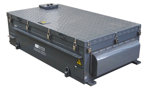
Picture of system S545V19-K8-A

Features

Part Number S545V19-K8-A
Basic Module MUCK24V2870
Module Connection Type 24 series
Nominal Capacitance(F) 583
Operating Voltage Window(V) 410~547
Surge Voltage(V) 605
Stored Energy (kWh) 9.5
Standard Charge Current (A) 300
Standard Discharge Current (A) ≤300
Maximum Charge/Discharge Current(<20s) (A) 510
Operating Temperature(oC) -25~55(QC/T 741-2014)
-15~55(140A)
Storage Temperature (oC) -30~+65
Protection Level IP65(Except inlet and outlet)
Electric Property Overvoltage, overcurrent, overheat, overload, short circuit, DC leakage protection, etc
Capacitor Management System Automatic balance, voltage monitor, temperature monitor, DC leakage monitor, etc
Cooling Mode Air cooling
Communication Interface CAN
Size(mm) 1950*1170*645
Weight(kg) 1000

Method & Notice

Test conditions

Ambient temperature: 25±5℃

Relative humidity: 25%~85%

Ambient pressure: 86~106kPa

Standards and Conformity

IEC 61373-2010 Railway applications--Rolling stock equipment--Shock and vibration tests

GB 4208-2008 Degrees of protection provided by enclosure (IP code)

EN 60077-1 Railway applications--Electric equipment for rolling stock Part 1: General service conditions and general rules

EN 50124-1 Railway applications--Insulation coordination Part1: Basic requirements--Clearances and creepage distances for all electric and electronic equipment

GB/T 24338.4 Railway applications-Electromagnetic compatibility

QC/T 741-2014 Ultra-capacitor for electric vehicles

Operating requirements

System should be placed vertically upward during operation

As a high voltage device, the system shall not be used, disassembled or maintained by non -professionals.

When connecting the system to external circuit, the circuit switch must be cut off first, otherwise there would be danger of high-voltage shock

Before operating the system, connect communication cables to vehicle system correctly, and make sure the positive and negative polarity of power supply and load

Short-circuit and reverse connection of the system is strictly prohibited, cut off circuit and take safety measures once such cases happen

Check each parameter on the human-computer interface(HMI) to ensure the voltage of each cell is between 2.85~3.8V and the maximum voltage difference shouldn’t be larger than 300mV

Collision, strike, crush to the system case is strictly prohibited, forbid opening the box during operation, forbid contacting live part such as positive or negative terminal and power cables with any material

Please stop charging when peculiar smell or abnormal noise is found during charging the system

Abandoning used capacitor is strictly prohibited, please discharge capacitor to 0V before recycling

Storage and transportation requirements

Ambient temperature: -30~65℃

Relative humidity: 0~95%

Ambient pressure: 86~106kPa

System should be placed vertically upward during storage and transportation

Keep power interfaces protected in order to prevent collision, which may cause short circuit during the process of storage and transportation

System must be charged to rated voltage before long term storage and transportation. Check cell voltage difference every 4 months, when cell voltage difference is<300mV and >50mV, balance system should be activated until the cell voltage difference drops to ≤40mV, when cell voltage difference is>300mV, child node or capacitor should be checked, replace the bad child node or cell if necessary

When system is kept unused for longer than 1 year, it should be tested by Aowei before using.

See the product catalogue for more information

Copyright © 2022 AOWEI TECHNOLOGY Shanghai ICP 2020037863-1   |  Download  |  Disclaimer |  Map